
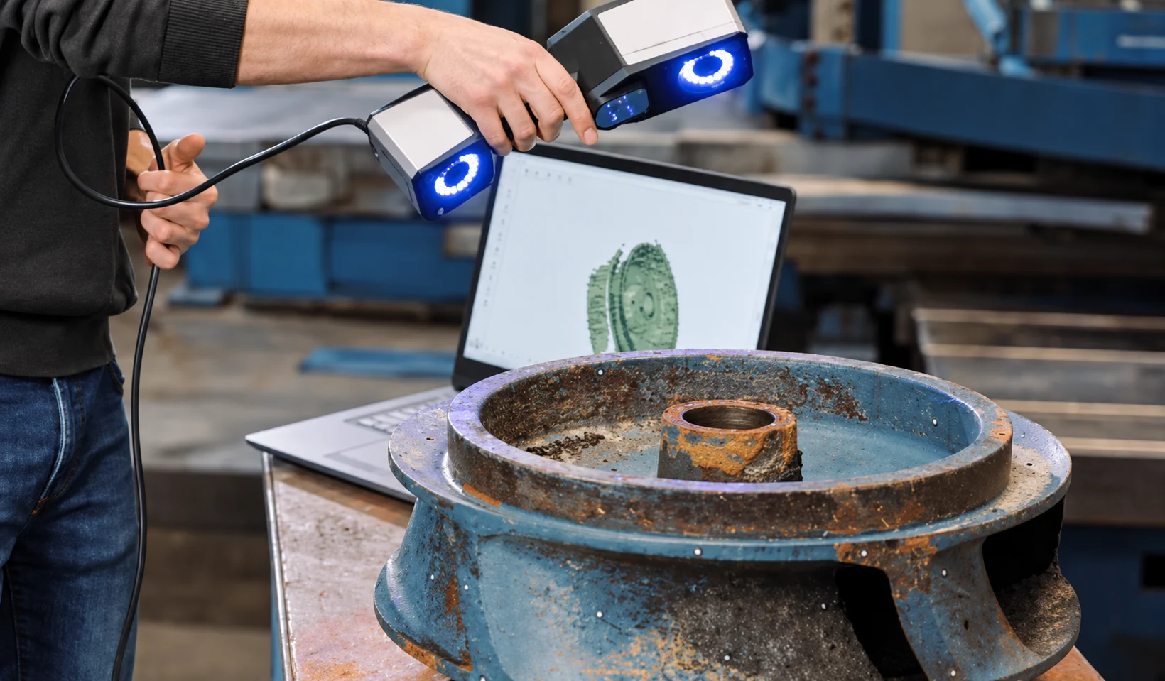
CNC machining without drawings refers to producing high-precision parts without client-supplied CAD models or 2D blueprints, by reverse engineering the physical sample into a parametric CAD file for CAM execution. In industrial maintenance, R&D, and legacy equipment support, a common bottleneck is the missing drawing. The part exists physically, but no CAD file, no 2D drawing, and no OEM support. Traditional CNC machining requires a drawing; without one, most machine shops decline the job. This guide explains how to go from a physical sample to a fully validated CNC-machined replacement — no drawings required.
Why Most CNC Shops Cannot Machine Without Drawings
A conventional CNC workflow starts with a CAD file. The shop imports the file, generates toolpaths, and machines the part. Without a drawing or CAD, the workflow stops. Manual measurement can produce a sketch, but it cannot capture:
- Freeform surfaces (impeller blades, complex contours)
- Internal features (cross-holes, undercuts, threads)
- Worn geometry where the original nominal dimension is lost
- GD&T requirements (ASME Y14.5 / ISO 1101) for mating alignment
This is where reverse engineering services and 3D scanning replace the missing drawing.
The 5-Step Workflow: From Physical Sample to CNC-Machined Part
1
High-Density 3D Scanning
We capture the physical sample — even if worn or damaged — using industrial blue-light 3D laser scanners.
- Volumetric scanning accuracy: up to ±0.02 mm
- Critical features: CMM-verified down to ±0.005 mm
- Output: raw point cloud + STL mesh
2
Wear Compensation and Deviation Analysis
The scanned part is not the original part. We perform wear compensation analysis to distinguish service-induced damage (corrosion, deformation, abrasion) from the original design geometry. Using deviation analysis (color mapping), we compare the point cloud against reconstructed nominal features.
3
Parametric CAD Reconstruction
Our engineers rebuild the part as a fully editable, parametric CAD model. We deliver native SolidWorks (.sldprt), Autodesk Inventor, and neutral STEP / IGES / Parasolid (.x_t) formats.
- GD&T per ASME Y14.5 / ISO 1101
- Functional tolerance allocation: critical fits ≤ 0.01 mm
- Clean feature trees ready for CAM programming
4
CAM Programming and First Article Machining
Using the reconstructed CAD, we generate CAM programs and machine a first article. The first article is inspected on a bridge-type CMM to validate critical dimensions and GD&T against the CAD model.
- Output: FAI report (AS9102 structure) + dimensional inspection report
5
Batch CNC Machining and Quality Documentation
After first article approval, we machine the batch using precision CNC machining services in metals or engineering plastics.
- Machining tolerances (ISO 2768): Metals ±0.05 mm (ISO 2768-f) / Plastics ±0.1 mm (ISO 2768-m) / 3D printing, vacuum casting, sheet metal ±0.2 mm
- Surface finish: Ra 0.8 μm – Ra 3.2 μm
- Documentation: CMM report, FAI (AS9102), Material Certification (MTR)
- Delivery: DHL / FedEx worldwide
Comparison: Mechonus No-Drawing CNC vs. Traditional CNC Shops
| Feature | Mechonus No-Drawing CNC | Traditional CNC Shops |
|---|---|---|
| Drawing Required | No. Physical sample is sufficient. | Yes. CAD file or 2D drawing required. |
| Reverse Engineering | Included. 3D scanning + parametric CAD. | Not offered. |
| Wear Compensation | Yes. Distinguishes damage from original geometry. | No. Cannot machine worn parts. |
| CMM Validation | Included. First article + batch inspection. | Optional, often not offered. |
| Lead Time | 2–4 weeks (e.g., Ø100 mm turbine blade: ~1 wk scanning-to-CAD + ~1 wk machining). | Weeks to months (if drawing exists). |
| MOQ | 1–500 pieces. Accept 1-piece prototype. | High MOQ. |
| Documentation | CMM Report + FAI (AS9102) + MTR. | Drawing only. |
Industry Applications
- Automotive (IATF 16949): Obsolete powertrain components, engine brackets, transmission housings. PPAP Level 1–3, IMDS, Control Plan supported.
- Medical (ISO 13485): Surgical instruments, prosthetic components, device enclosures. DHR and full lot traceability supported.
- Heavy Industry: Compressor impellers, pump housings, mining equipment parts. See our compressor impeller reverse engineering case study and slurry pump housing case study.
FAQ
Can you CNC machine a part without a drawing?
Yes. We reverse engineer the physical sample using 3D scanning and parametric CAD reconstruction, then CNC machine the replacement. No original drawings are required.
How do you handle worn or damaged parts?
We perform wear compensation analysis. We distinguish service-induced damage from original design geometry, then reconstruct the nominal CAD model rather than replicating the worn shape.
What is the typical lead time for a no-drawing CNC project?
Standard lead time is 2–4 weeks from sample receipt to delivery, excluding international shipping and special process machining time. This includes 3D scanning (2–5 days), CAD reconstruction (3–7 days), first article machining and CMM inspection (5–10 days), and batch machining. Expedited service is available.
What files do you deliver?
We deliver fully editable parametric CAD in STEP, IGES, Parasolid (.x_t), and native SolidWorks (.sldprt) formats. Every project includes a 3D deviation analysis report and CMM dimensional verification.
What quality documentation do you provide?
We provide CMM Dimensional Inspection Reports, First Article Inspection (FAI) Reports following AS9102 structure, and Material Certifications (MTR). For automotive clients, we support PPAP Level 1–3. For medical clients, we support DHR and full lot traceability.
Do you have a Minimum Order Quantity (MOQ)?
No strict MOQ. We accept 1-piece prototype orders. A small setup fee applies to cover programming and fixtures, waived on reorders after first article approval.
Conclusion
CNC machining without drawings is not only possible — it is a controlled engineering workflow. From 3D scanning to parametric CAD to CMM-validated machining, Mechonus delivers verified replacement parts for obsolete, undocumented, or worn components. For a deeper look at cost factors, read the real cost of obsolete parts reverse engineering.