
The Problem Is Not the Part. It Is the Downtime.
When a critical component fails and the OEM says “discontinued,” maintenance teams face familiar options. Search the aftermarket for old stock. Call every distributor within driving distance. Consider a 3D printed stopgap. Or accept a six-month lead time for a new machine that may cost more than the annual maintenance budget.
None of these, on their own, recovers the missing engineering definition. They are workarounds.
A 2025 Fluke survey of more than 600 senior decision-makers and maintenance professionals across the U.S., U.K. and Germany reported that 61% of manufacturers experienced unplanned downtime in the previous year. Fluke estimated losses of up to $852 million weekly, reported an average cost of $1.7 million per hour, and described incidents reaching $42.6 million. These are survey-level findings, not a universal hourly rate for every factory. Read the original Fluke report.
That is the real context for a discontinued part: restoring production before the losses compound. Most reverse engineering content focuses on scanning equipment or CAD software. The question is not “can you scan a part?” It is whether a worn, damaged, undocumented component can become a manufacturable, verifiable replacement that restores function.
What Most Teams Try First (And Why It Falls Short)
The Salvage Hunt
Searching marketplaces, calling distributors or hoping a warehouse has old stock is a gamble. It might buy months, but it does not rebuild a supply chain that no longer supports the part. Recovered stock still needs condition and suitability checks.
The “Quick” 3D Print
Additive manufacturing can be fast and useful for prototypes or suitable replacement applications. High loads, temperatures and critical fits require a qualified material, process and finish. An unqualified printed stopgap can create a second failure rather than a saving.
The “Just Copy It” Trap
Using the worn part as a blueprint without accounting for deformation, corrosion or wear transfers damage into the replacement. All three approaches risk treating the symptom rather than the system. A controlled process starts with function—not an unquestioned copy of the as-is surface.
A Controlled Reverse Engineering Workflow: From Evidence to Manufacturable Data
The following workflow draws on Mechonus projects in hydropower, mining, commercial vehicles and semiconductor equipment. Each application needs its own acceptance criteria and customer approval.
Step 1: Component Identification — Understand Function Before Geometry
Before scanning, identify function, mating interfaces, service conditions and failure mode. Engineering judgment determines which features control the outcome and where further evidence is needed.
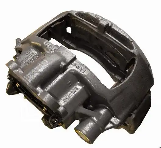
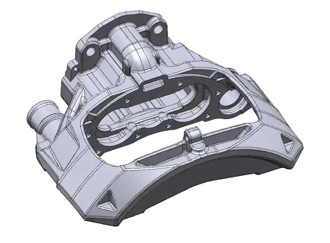
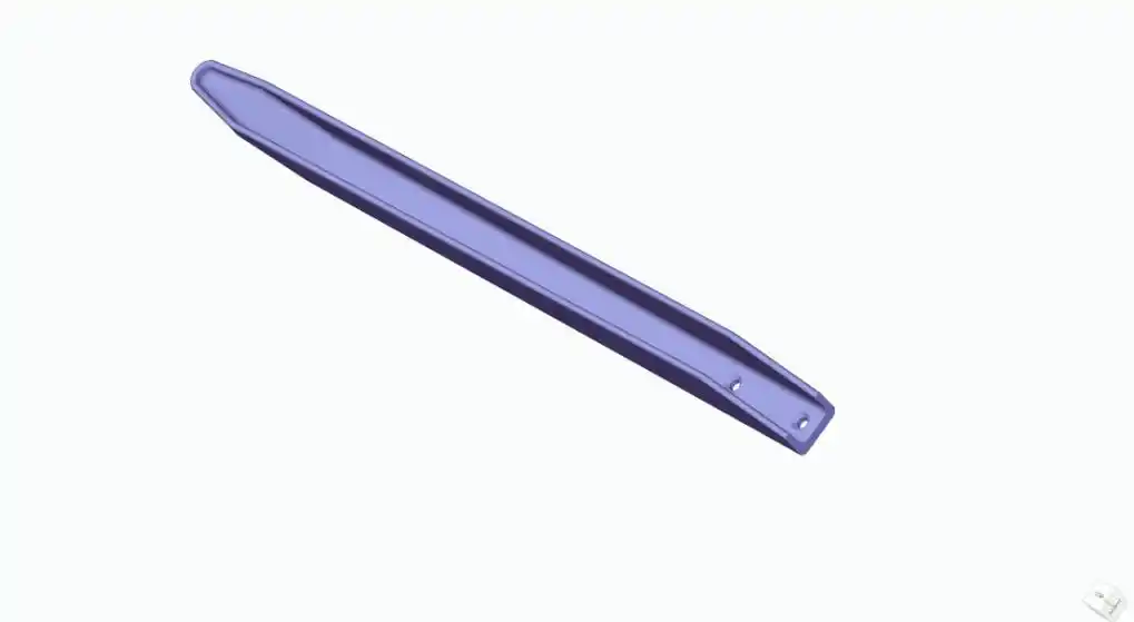
Real example: heavy truck brake caliper cover. Rather than copying worn cast surfaces, the team focused on wall thickness, mounting holes, assembly relationships and structural requirements. Core machining areas were controlled to ≤0.1 mm; non-critical cast surfaces used approximately 0.2–0.3 mm allowances. Tight tolerances everywhere add cost without necessarily improving function. Explore the brake caliper reverse engineering case.
For a safety-critical braking component, dimensional compliance alone does not authorize service release. Material, strength, testing and applicable approvals must also be established.
Step 2: Precision Measurement — Capture the True Geometry
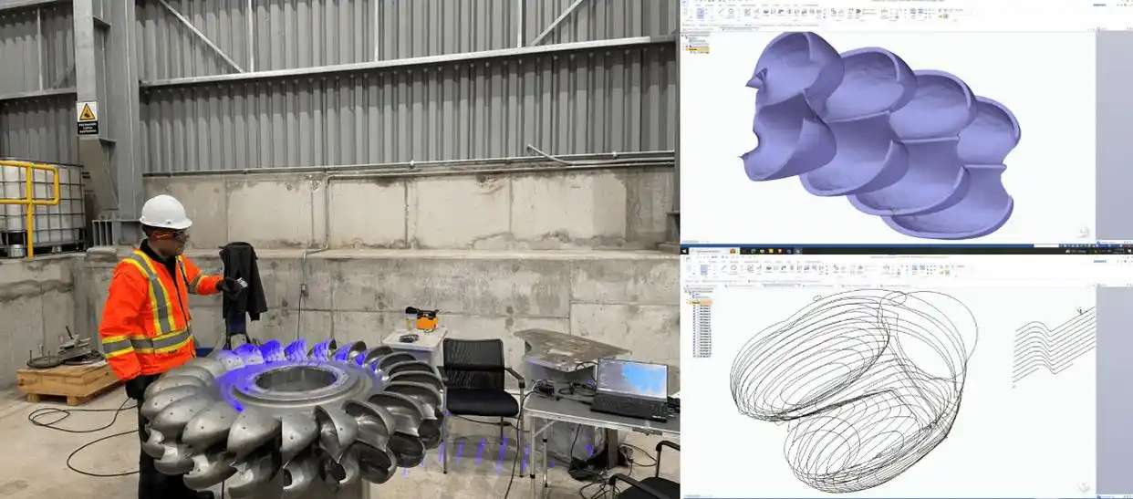
Industrial blue light 3D scanning captures the as-is condition. The goal is sufficient evidence to understand nominal geometry before wear—not reproduce damage. Setup, calibration, surface condition and access affect measurement confidence.
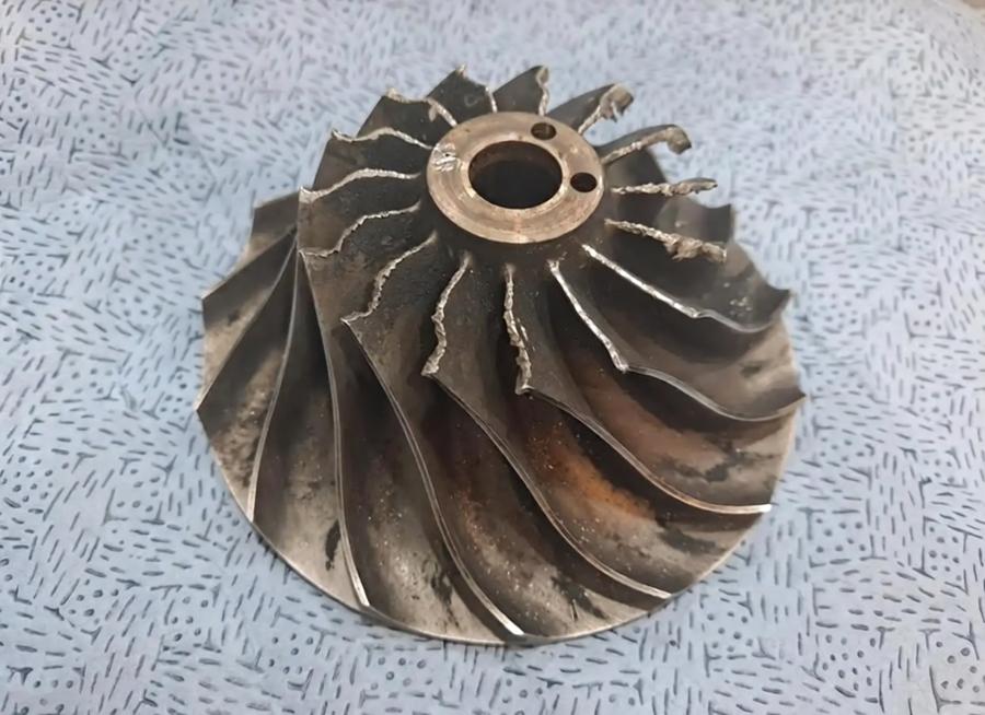
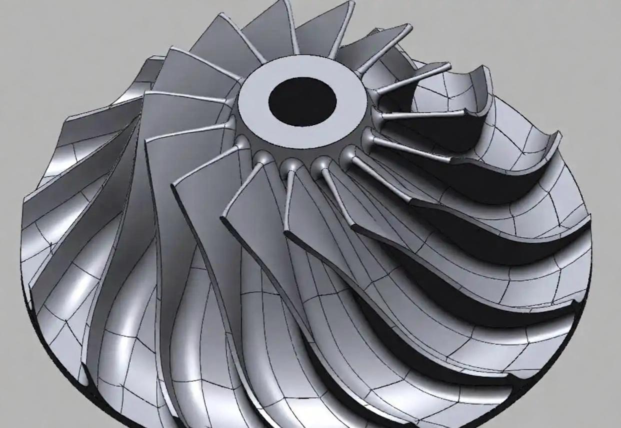
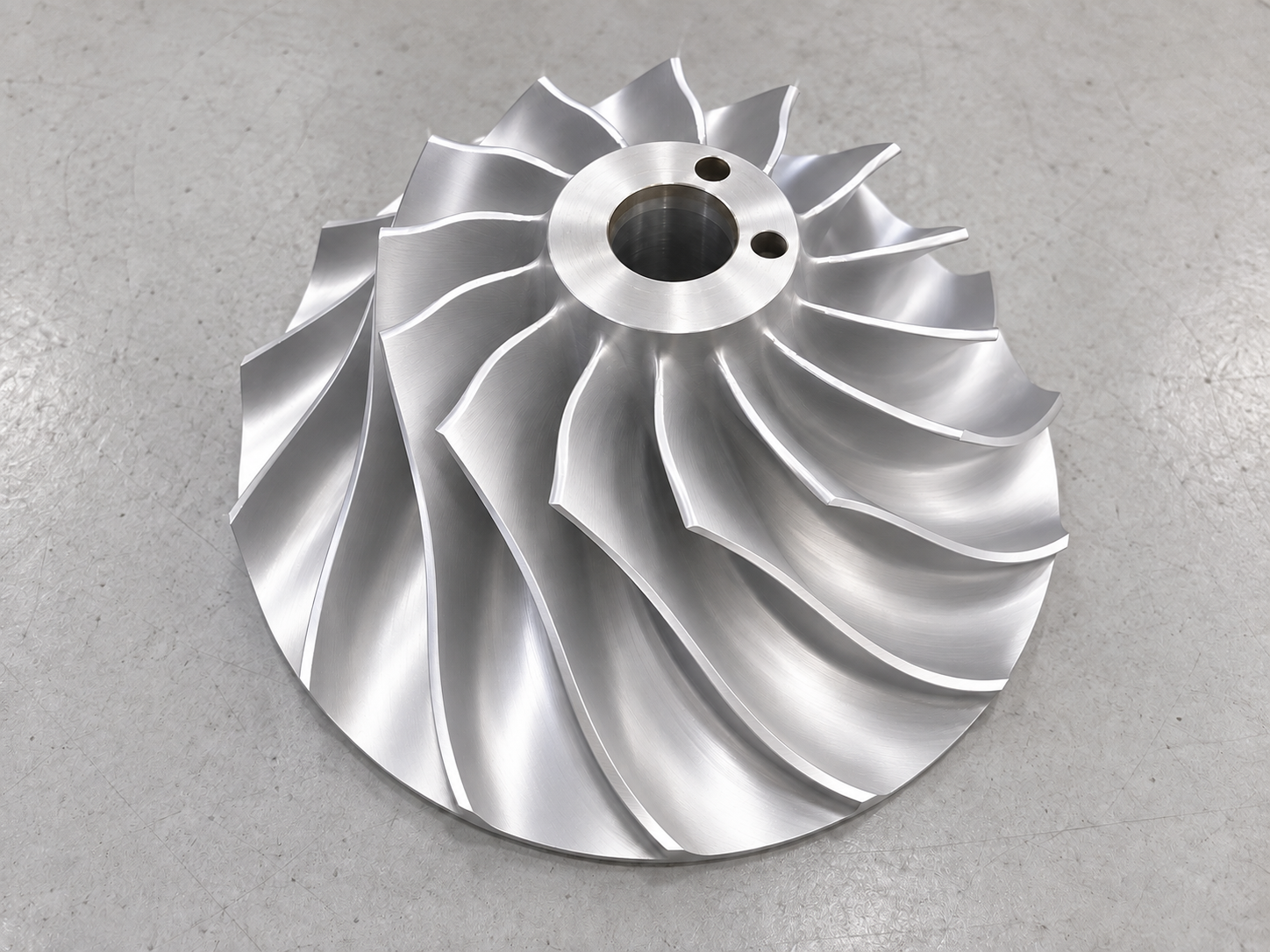
Real example: 3 MW Kaplan turbine blade. Severe cavitation had reduced output to approximately 2 MW. Full-surface scanning, including damaged areas, became the foundation for reconstruction and optimization rather than simple replication. See the Kaplan turbine blade project.
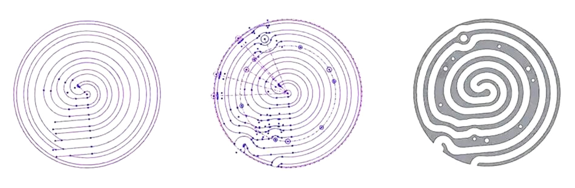
Real example: Ø374 mm wafer heater disk. With drawings lost, a ZEISS GOM Scan 1 blue light scanner captured spiral heating channels and hole relationships. The project describes 0.01 mm-level scanning capability and six million points per frame. Instrument capability is not a blanket finished-part tolerance; critical features still require appropriate verification. Review the wafer heater disk reconstruction.
Step 3: CAD Reconstruction — From Point Cloud to Manufacturable Model
Scan data alone is not a complete manufacturing definition. Nominal geometry must be rebuilt into editable CAD with functional datums, fits and geometric dimensioning and tolerancing (GD&T).
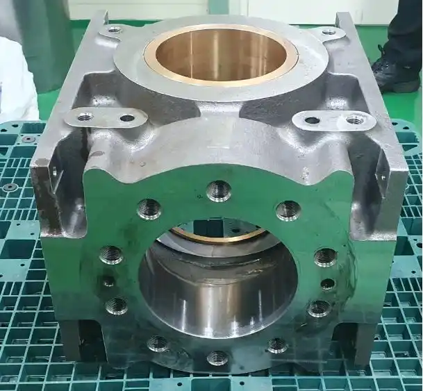
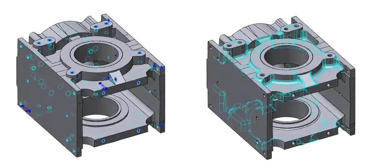
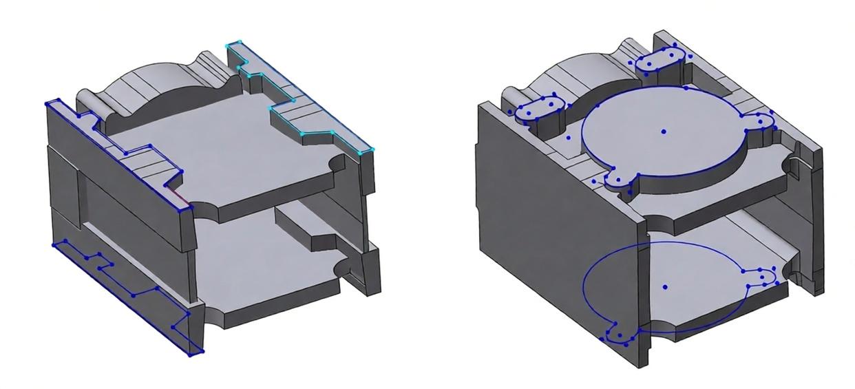
Real example: 600 × 500 mm pump body casting. The discontinued housing required recovery of the shaft sleeve center and control of perpendicularity and parallelism within 0.1 mm. CNC geometry was prepared without casting draft. A casting route would separately require draft, shrinkage and machining allowances. Follow the pump body reverse engineering decisions.
A mesh is a surface representation. Controlled CAD, drawings and inspection requirements define how the component should be made and verified. STEP or IGES exchange files are useful, but native parametric history must be requested separately when required.
Step 4: Validation — Material, Fit, and Function
Validation connects the reconstructed model to service requirements. It may include material identification, dimensional inspection, assembly trials, simulation and application-specific testing.
Real example: Kaplan turbine blade optimization. Multiple CFD iterations adjusted the blade centerline to reduce cavitation. A guide ring at the hub improved water flow. After casting and installation, the unit returned to rated 3 MW output and reported design efficiency. This was a project-specific improvement, not just a copy.
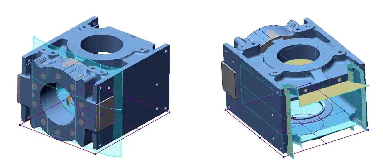
Real example: pump body casting validation. CAD was compared with original scan evidence using color-map analysis. Core machining areas were controlled within 0.1 mm, and the project reported a threefold increase in assembly efficiency. These results are case outcomes, not guarantees for every project.
What This Means for Your Operation
The projects did not start with “what can we scan?” They started with “what is failing, why, and what will restore function?”
- Reduced downtime exposure: an agreed engineering and manufacturing plan offers an alternative to uncertain stock searches and lengthy OEM lead times. Timing depends on scope.
- Cost avoidance: technically feasible component-level recovery can avoid replacing a complete turbine unit or pump assembly.
- Reusable manufacturing data: controlled CAD supports tooling, CNC machining and future spare-part production, not only a one-time repair.
“We had planned to give up on this repair business. Mechonus not only replicated the part data but delivered CAD files ready for tooling. Now we can repair and produce our own spares.”
Anonymized customer feedback from the brake caliper project
A Practical Checklist Before You Scrap That Obsolete Part
- Document the failure mode. Record what failed, why and the operating conditions. Wear shows stress locations, not automatically design intent.
- Identify critical interfaces. Mounting holes, bores, seals, threads and mating faces control fit and function.
- Do not assume the worn part is the blueprint. Wear, deformation and corrosion are damage, not design features.
- Ask for manufacturable output. Agree editable CAD, GD&T drawings, material requirements and inspection evidence—not just a mesh.
- Engage a reverse engineering partner early. Review feasibility and validation before committing resources to a replacement route.
Send photographs, approximate dimensions, mating-part details, material information, quantities and failure history. Contact Mechonus engineering for a project review.
Frequently Asked Questions
What is reverse engineering in manufacturing?
Reverse engineering recreates engineering data from a physical part through 3D scanning, CAD reconstruction, material identification and validation. The goal is to recover design intent and define a manufacturable replacement—not copy service wear.
When is reverse engineering the right choice?
It is useful when OEM parts are discontinued, drawings are lost, lead times are unacceptable or suppliers no longer support legacy equipment. Feasibility depends on material, service conditions, available evidence and validation requirements, particularly for safety-critical components.
Can you reverse engineer a part with no drawings?
Yes. Precision measurement of the physical part, mating interfaces, symmetry and service history can support reconstruction without drawings. Missing or damaged features require engineering review rather than unsupported assumptions.
What files do you deliver?
The agreed package can include an editable native parametric CAD model, STEP or IGES exchange files, 2D drawings with critical dimensions and GD&T, and an inspection report. Exchange formats do not necessarily preserve native feature history. Documentation and formats are agreed during quotation.
How do you ensure dimensional accuracy?
We use calibrated measurement equipment, blue light scanning and targeted metrology such as CMM inspection. Color-map comparison supports surface validation; critical bores, fits and datum relationships also need feature-specific inspection. Tolerances are assigned by function, not uniformly across every surface.
What industries do you serve?
Mechonus works across hydropower, mining, automotive, semiconductor equipment, industrial MRO and heavy equipment. The common need is a critical component that is unavailable or lacks usable engineering documentation.
About This Article
This article synthesizes anonymized Mechonus project documentation in hydropower, mining, commercial vehicles and semiconductor equipment. Technical parameters and outcomes refer to individual projects, not universal capabilities, savings or certifications. Actual machining conditions vary with equipment, tooling, material and geometry.
Illustrations reuse corresponding case-study assets for editorial review. They are not independent inspection records or proof of performance.
Sources
- Fluke Corporation: 2025 multinational industrial downtime survey, published October 30, 2025.
- Mechonus project documentation, anonymized and summarized: Kaplan turbine, pump housing, brake caliper and wafer heater disk.
Related capabilities: reverse engineering, CNC machining and quality and inspection.