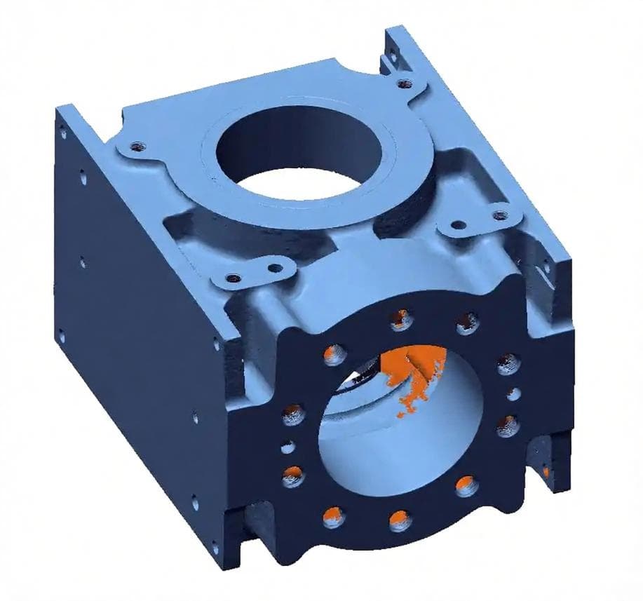
Representative reverse engineering case · mining

Mining Slurry Pump Recovery: From Worn Casting to CNC-Finished Part

A discontinued slurry-pump housing casting at a North American mine was transformed from worn physical evidence into a customer-approved CNC component, full inspection package and repeatable digital asset—raising assembly efficiency by 3×.

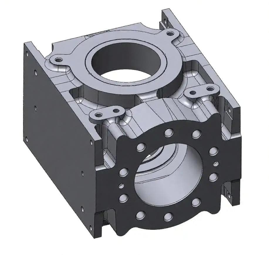
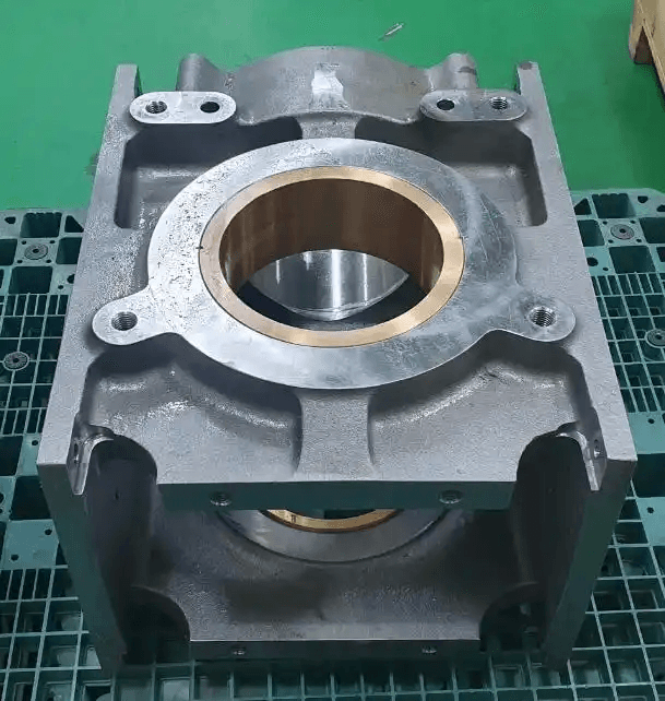
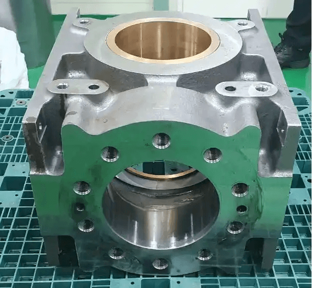
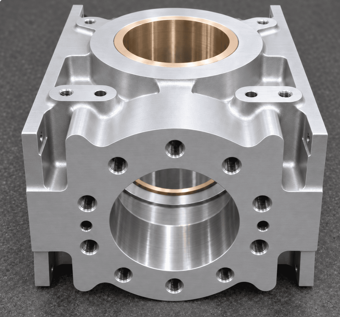
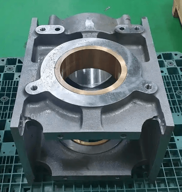
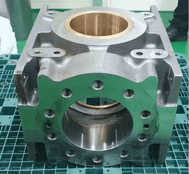
Original worn pump housing, top viewOriginal worn pump housing, front viewNew CNC-finished pump housing
Physical sample views followed by the newly manufactured CNC-finished replacement.

The challenge

A critical slurry pump suddenly went down.

At a North American mineral-processing plant, a critical slurry pump developed severe vibration and was stopped for inspection. The internal power-transmission casting within its housing showed extensive wear and local cracking; it could not continue in service.

The pump moved mineral slurry from the mill discharge to the cyclone cluster. A shutdown longer than 48 hours threatened to interrupt the processing route. The 1990s-era pump model had been discontinued, no spare was available and the only sample was too worn for direct measurement. The mine had to choose between a costly new pump package and a controlled way to make the legacy housing usable again.

The challenge

Wear, cracking and no drawing at the exact point production depended on.

The sample contained the only remaining geometry evidence, but it also carried the service damage that could not be reproduced. The engineering task was to recover functional interfaces, internal passage geometry and assembly relationships without copying the damage into the new part.

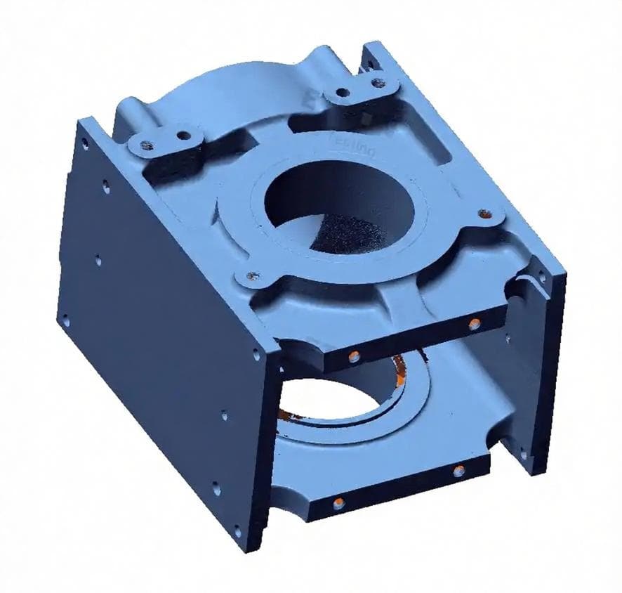
Original worn pump housing, top viewPump housing CAD model, first view
Physical sample and recovered CAD model: top-side comparison.
Original worn pump housing, front viewPump housing CAD model, second view
Physical sample and recovered CAD model: front-side comparison.

The approach

From physical part to an installable finished component.

Mechonus supplied more than scanning and modelling. The project ran through six controlled stages—from damaged sample to customer-approved casting, CNC finish machining, inspection and delivery—with every engineering decision linked to the released data revision.

01

Capture the real geometry

A high-precision blue-light scan captured the worn housing across external forms, internal passages and small features. For the rough casting surface, the acquisition strategy focused on functional geometry rather than pits, surface texture and other non-functional interference.

  • 0.01 mm-class scan capability
  • 5 million+ points at 0.03 mm resolution
  • Complete internal passages and small-hole coverage
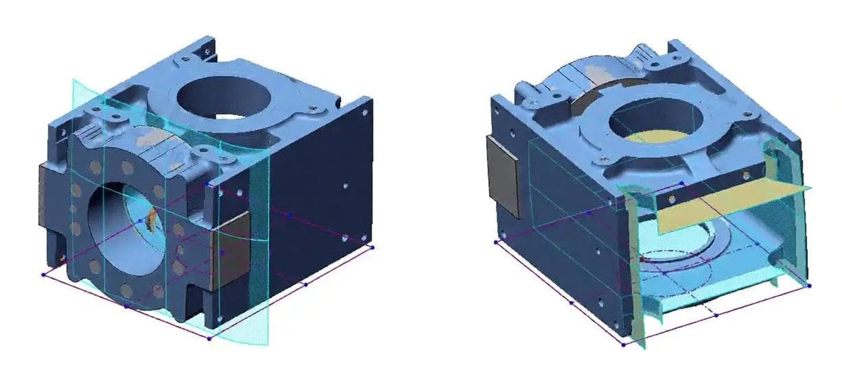
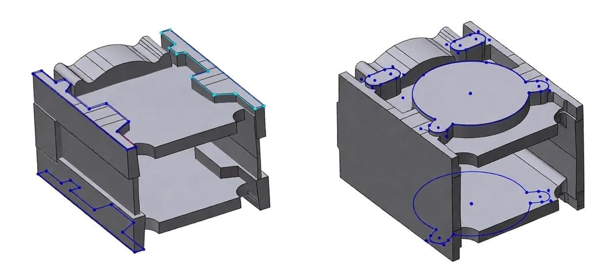
Pump housing section and datum analysis
Section analysis and measurement planes used to recover the housing geometry.
Pump housing CAD structure and controlled feature profiles
Recovered CAD structure and controlled feature profiles.
02

Rebuild a castable, manufacturing-ready CAD definition

The point cloud was not treated as a finished model. Section analysis established datums and concentric sketches; the housing body, locating features and mounting holes were rebuilt as native parametric geometry around the part’s functional requirements. The goal was not visual tracing, but recovery of the original design intent in a model that could drive casting and subsequent machining.

  • Functional datum extraction from measured sections
  • 1:1 solid reconstruction with casting-process features
  • Measured centre-distance compensation for locating and fastener features
Pump housing parametric CAD reconstruction
Parametric CAD reconstruction with recovered interfaces and feature geometry.
03

Obtain customer design approval before production

The reconstructed CAD, critical dimensions, GD&T and assembly interfaces were issued for customer technical review. Production began only after the release was approved, preventing unrecorded assumptions from entering the casting or machining route.

  • CAD and drawing review
  • Critical interface confirmation
  • Approved revision becomes the production baseline
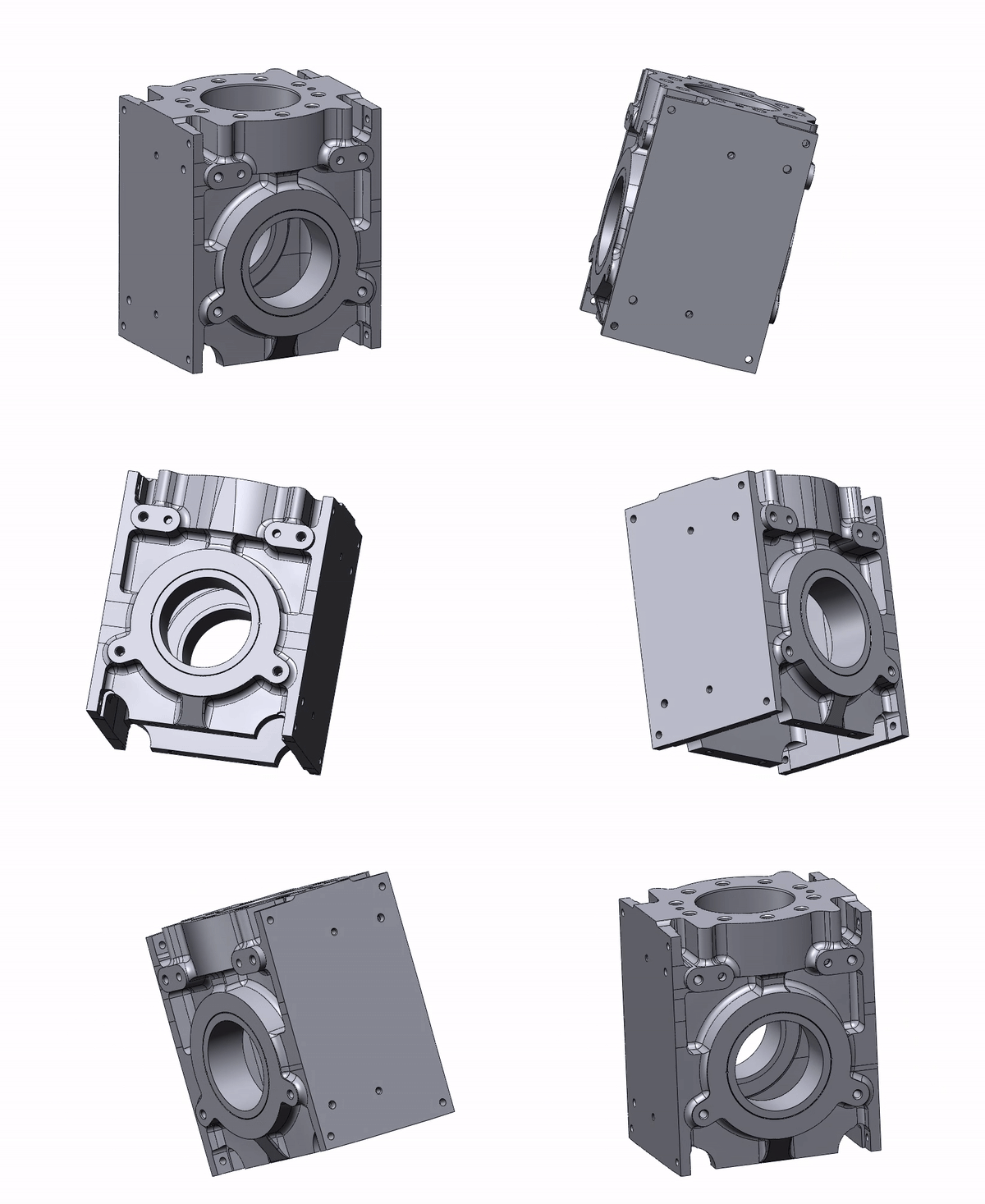
Approved pump housing CAD model, first viewApproved pump housing CAD model, second view
Customer-approved CAD views before production release.
04

Produce and inspect the cast blank

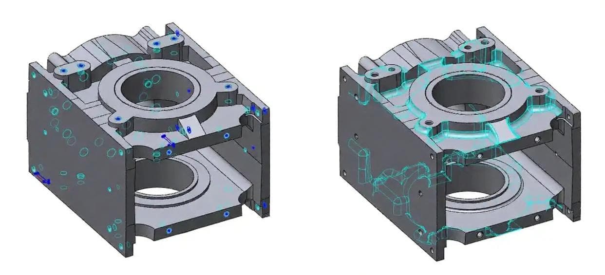
After approval, the CAD model was released to the foundry partner for pattern / tooling preparation and casting. The new blank was inspected before machining to confirm that sand inclusions, shrinkage porosity and other casting defects would not compromise the finished component.

  • CAD-controlled pattern and tooling preparation
  • Casting of the replacement blank
  • Initial blank inspection for sand holes, shrinkage and defects
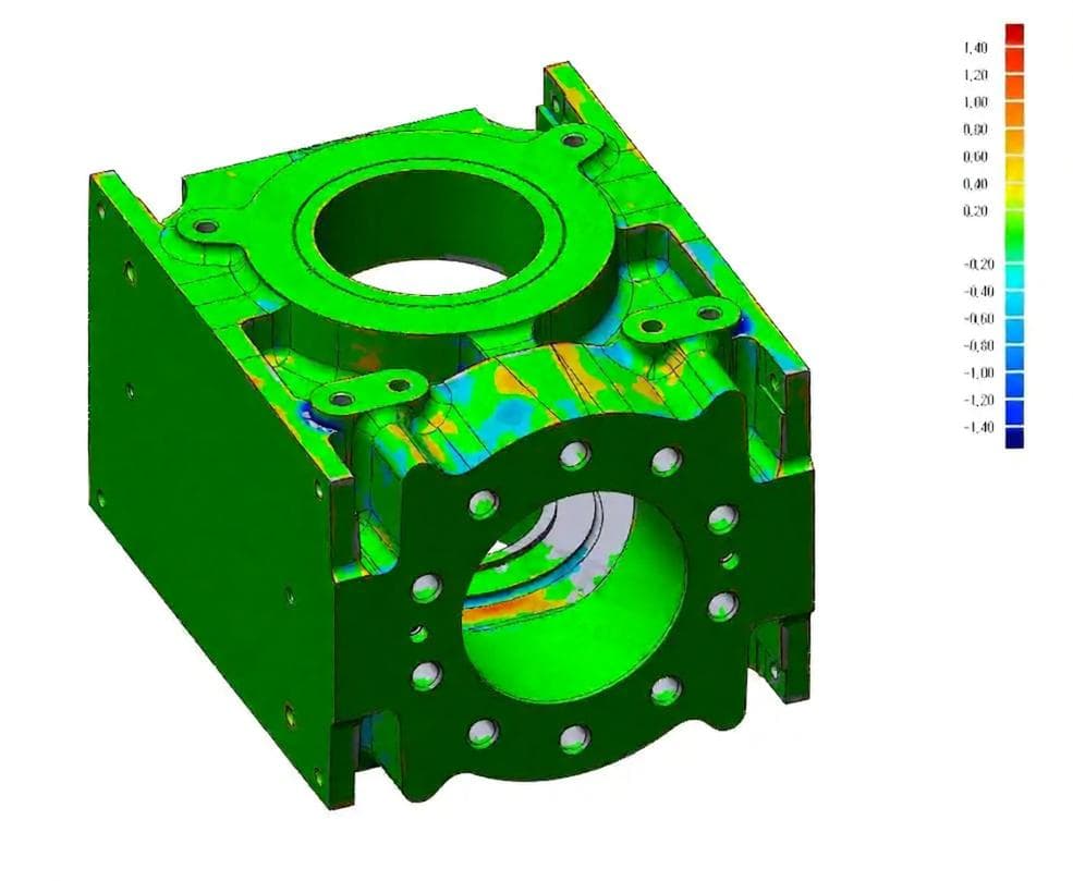
Pump housing casting inspection colour map
Casting inspection colour map before machining release.
05

CNC finish the cast blank into a precision component

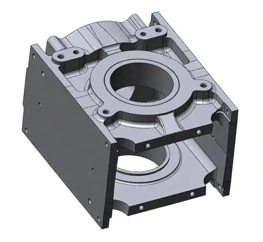
Once the casting blank passed inspection, it entered the CNC finishing route. Dedicated workholding established rigidity and locating accuracy while critical fits, bores, sealing faces and mounting holes were machined, deburred and finished to the approved drawing.

  • Dedicated fixture for rigidity and locating accuracy
  • Precision machining of fits, hole positions and sealing surfaces
  • Deburring and surface-finish control to drawing requirements
Animated CNC-ready pump housing model
CNC-ready pump housing model.
06

Inspect and deliver for first-time installation

Critical dimensions, GD&T and assembly interfaces were inspected before release. The completed part was delivered with full inspection evidence, colour-map comparison and export-ready packaging for international transport.

  • 100% inspection of critical interfaces
  • Colour-map result for ≤0.1 mm core-feature deviation
  • Finished part + inspection package + transport packaging
New CNC-finished slurry pump housing
CNC-finished replacement ready for inspection and delivery.

The result

Assembly efficiency improved 3×—from repeated fitting to first-time installation.

Controlled geometry turned a repair activity once dependent on repeated hand fitting into a defined installation route. The finished housing delivered the accuracy, documentation and repeatability required for the mine’s maintenance team.

Core-feature deviation≤0.1 mm
Assembly efficiency3× improvement
Assembly routeFrom repeated fitting to first-time installation
DeliveredCNC-finished component + full inspection report

Deliverables

An installable CNC component plus a complete data package.

The customer received a physical replacement and a reusable, traceable digital baseline. When a similar component needs service in the future, engineering can start from controlled CAD rather than from a craftsman’s memory.

01

CNC finished component

Machined from the customer-approved CAD definition, with core functional features controlled to ≤0.1 mm.

02

Standardised CAD data

A parametric model with key dimensions, GD&T and manufacturing datums retained for future use.

03

Full-dimensional inspection report

Colour-map analysis and dimensional evidence supporting the released, installable component.

Customer feedback

“Assembly efficiency improved threefold. Our maintenance crew no longer spends hours hand-fitting the part. This digital route moved us from experience-based repair to data-based maintenance.”Maintenance Lead, North American Mining Operation
Project publication note

This case is based on an actual delivered project. Customer information and selected technical parameters have been anonymized. To discuss a similar reverse engineering project, submit your part information through our website and our engineering team will provide an initial assessment.

What this case demonstrates

From physical evidence to an installable CNC part.

This case brings together high-density data acquisition on rough cast surfaces, function-led parametric reconstruction and a closed loop from scan data through CNC manufacture and inspection evidence.

01

Capture through surface interference

0.01 mm-class blue-light scanning captures functional geometry without allowing casting pits and surface roughness to define the replacement.

02

Function-driven parametric CAD

Parallelism, concentricity, assembly datums and critical interface requirements govern reconstruction—not visual curve tracing.

03

Scan-to-CNC delivery

The customer receives an installable component and the controlled data required for repeatable future maintenance, not only a scan report.

Your worn casting is still engineering evidence

Start with the sample, the mating interfaces and the installation problem.

Share photos, dimensions, material information, operating conditions and any available pump records. We will define the capture, reconstruction and validation plan before manufacturing release.

Request an Engineering Review →

You control your choice. Continuing to browse does not constitute consent.

Strictly necessary — always active

Local browser storage remembers your consent choice for up to 180 days. It is not used for tracking.

Analytics and advertising — not used

No optional tracking technologies are currently installed. Accepting all does not enable any tracking. If this changes, we will update the policy and ask for fresh consent before enabling optional technologies.

Read our Cookie Policy.