Material
Aluminum alloy comparable to 7075-T6, selected for the agreed strength and machining requirements.

Representative reverse engineering case · industrial compressors
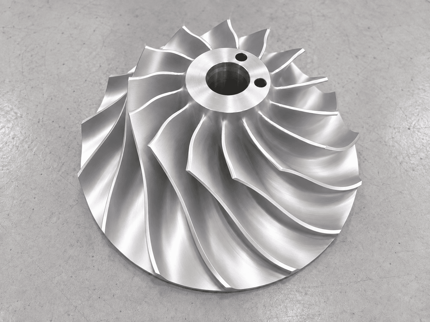
A second-stage centrifugal compressor impeller with cracked, partially missing blades became the evidence set for a controlled replacement program—combining 3D scanning, design-intent recovery, five-axis CNC machining and inspection.
The challenge
A critical centrifugal compressor at a Midwestern U.S. industrial gas plant was shut down after abnormal vibration. Inspection found multiple damaged inlet edges on the second-stage impeller, with two blades partially broken. The OEM could quote a replacement, but the stated lead time exceeded six months.
The impeller was a custom legacy design with no available CAD model and no recoverable original drawing. Used-part searches produced no viable alternative; local machine shops declined the work without drawings. The customer sent the damaged impeller to Mechonus for reverse engineering and replacement manufacture.
Material & specification
The project brief defined an aluminum alloy comparable to 7075-T6, twelve pieces including spare parts, dynamic-balance grade G1.0 and surface finish Ra ≤ 0.8 μm. These requirements were reviewed alongside the recovered geometry before release.
Aluminum alloy comparable to 7075-T6, selected for the agreed strength and machining requirements.
Industrial blue-light scan data with a 0.02 mm average point-spacing target for detailed blade and hub capture.
Ra ≤ 0.8 μm surface finish and G1.0 dynamic-balance requirement specified for the replacement route.
12 impellers including spares, with STEP data, controlled drawings and agreed inspection documentation.
The approach
Reverse engineering for compressor components requires both complete geometry capture and explicit engineering decisions for every area affected by damage, wear or missing data.
The returned impeller was cleaned, optically prepared and scanned from multiple orientations with an industrial blue-light system. A target average point spacing of 0.02 mm supported dense capture of the pressure side, suction side, hub passages and blade roots.
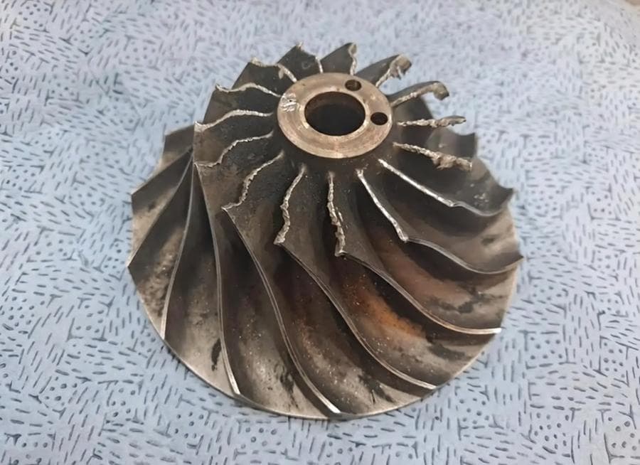
Two blades had partial edge loss and several inlet edges showed crack-related damage. Repeated blade features, hub geometry and intact regions were compared to recover the nominal relationships; missing sections were reconstructed from adjacent blade form and documented design assumptions.
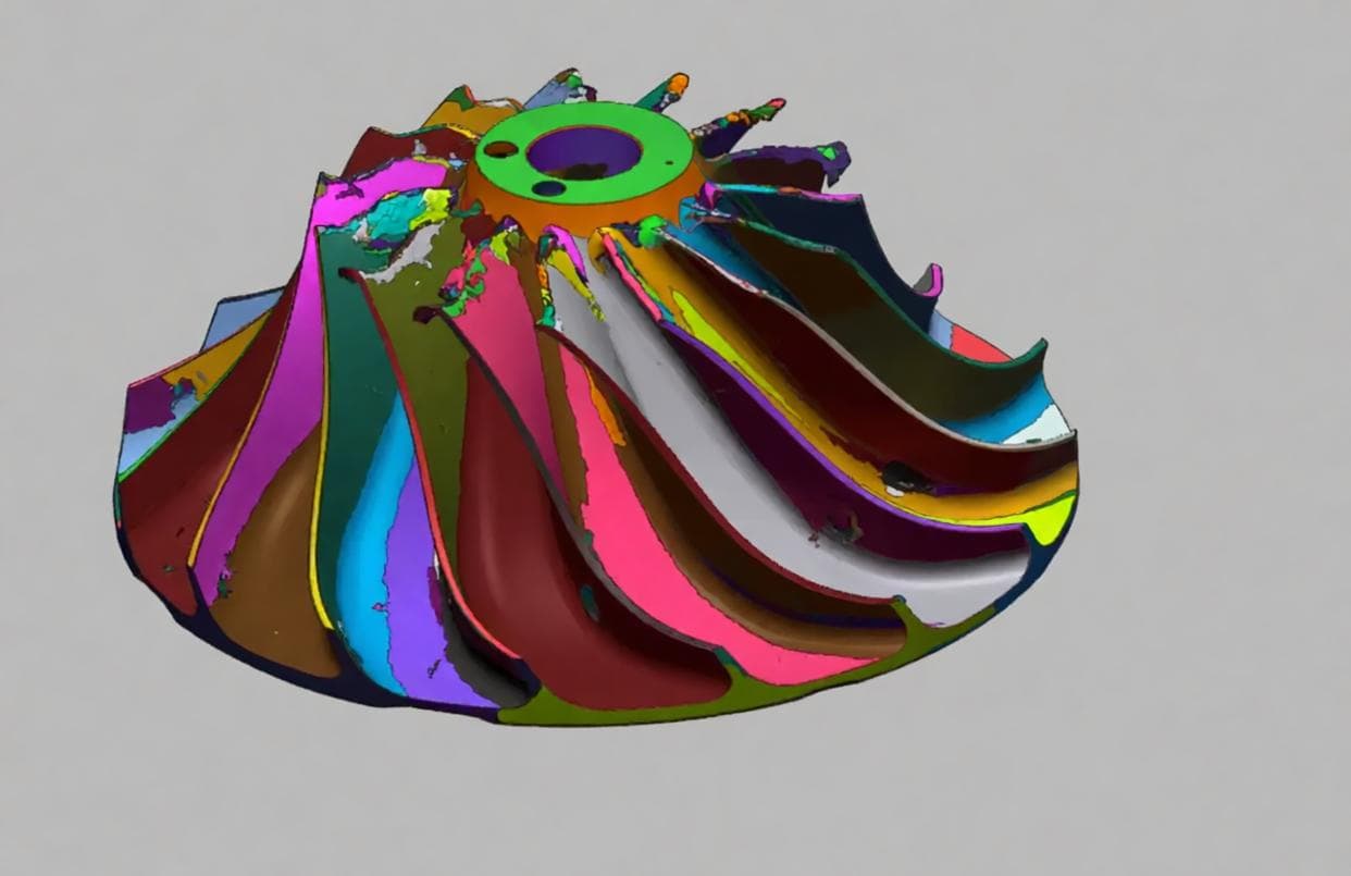
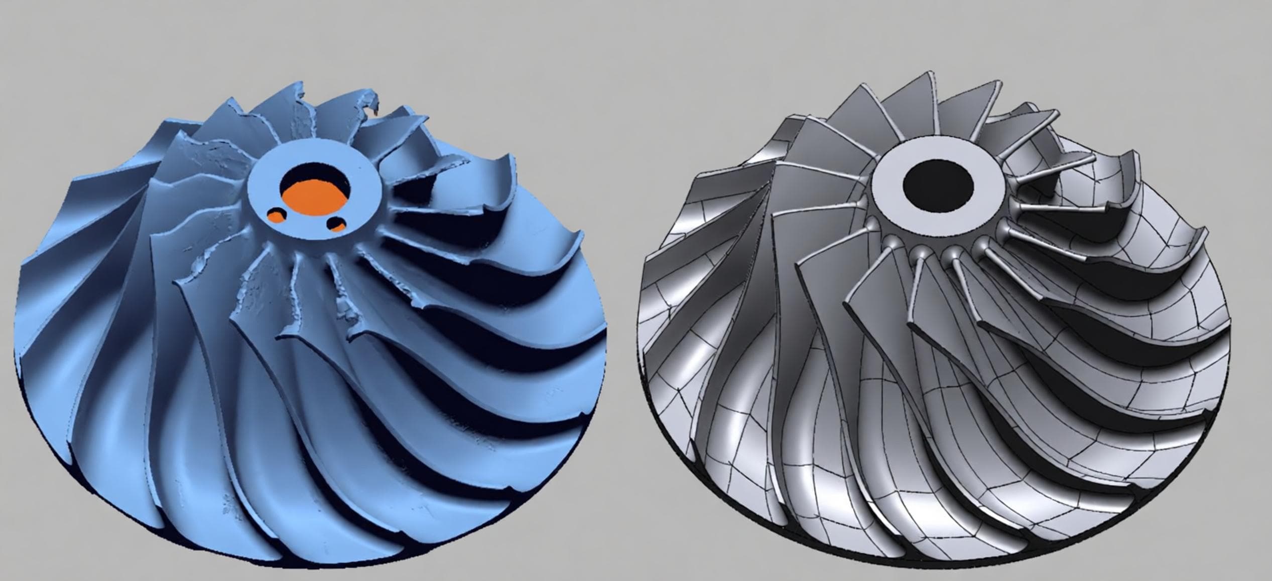
Geomagic Design X was used to turn scan evidence into editable parametric CAD. The approved model was released to five-axis CNC programming together with functional datums, bore fits, blade form requirements and a defined dynamic-balance plan.
Detailed engineering process
Every gate produces a specific engineering record. That is what turns a damaged legacy part into controlled manufacturing data rather than a one-time visual copy.
Photograph the impeller, record blade numbering and identify cracks, broken leading edges, rub marks and handling damage. Register bore, keyway, back-face, hub and mating-shaft evidence before cleaning changes the surface condition.
OutputDamage map + sample registerEstablish the rotation axis from the bore and datum faces; apply matte scan spray and reference targets to reflective aluminum. Plan overlapping views for blade roots, narrow passages, pressure surfaces and suction surfaces.
OutputDatum plan + scan setup recordCapture high-density mesh data from multiple orientations, align the data to the hub axis and inspect overlap quality. Targeted manual or CMM measurements confirm features that are inaccessible or critical to fit.
OutputAligned STL mesh + critical dimensionsRemove noise without smoothing away blade edges, classify holes and broken zones, and compare each repeated blade against intact neighbours. The team does not use scan-fill alone to define missing aerodynamic geometry.
OutputWear and missing-geometry mapBuild master sections, blade curves and hub surfaces in parametric CAD. Reconstruct repeated blade pattern, inlet and outlet edges, shroud-side relationships and the bore/attachment features around functional datums.
OutputEditable CAD + reconstruction assumptionsDefine critical dimensions, surface-finish requirements, bore fit, material condition, inspection points and dynamic-balance method. The customer reviews CAD, drawing and open assumptions before manufacturing release.
OutputApproved CAD, drawing + control planCreate a machining sequence that protects the bore and datum features, roughs the blade volume, finishes blade surfaces with controlled toolpaths, deburrs edges and preserves stock for final balance correction where specified.
OutputFirst article + job travelerInspect datum features, bore, hub, blade profile checkpoints and surface finish against the approved definition. Complete the specified balance procedure, review results with the customer and freeze the released data package for repeat orders.
OutputFAI/CMM report + balance record + released baselineManufacturing & verification
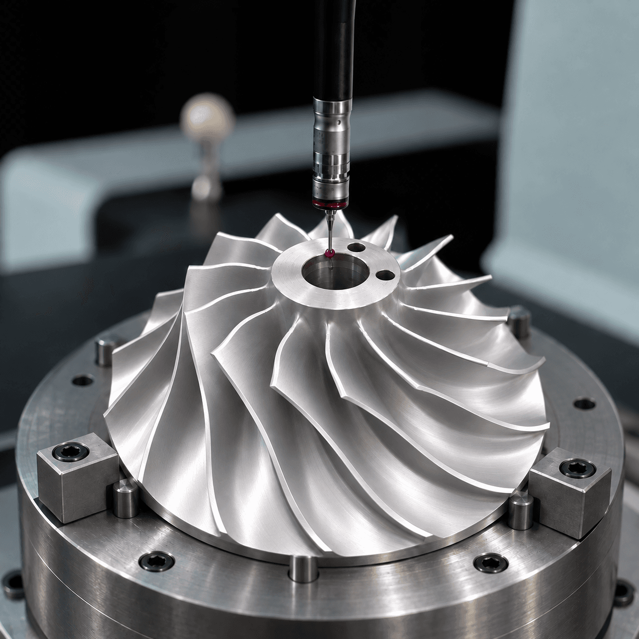
After customer approval of the reconstructed CAD, the impellers were machined on a five-axis CNC route, finished, inspected and dynamically balanced to the project requirement before release.
“The compressor ran smoothly after restart. Mechonus did more than reproduce a damaged sample—they gave us a controlled replacement path without waiting for the OEM.”Maintenance Manager, Industrial Gas Plant
This case has been published with customer authorization. Customer name, plant location and selected technical details have been anonymized. For a similar reverse engineering project, submit your part information through our website; our engineering team will provide an initial assessment within 24 hours.
Need a replacement impeller?
Send photos, dimensions, application details, any mating-component information and your required quantity. We will define the evidence and validation plan before quotation.