
When an original equipment manufacturer no longer supports a legacy steam turbine, reverse engineering can create a controlled replacement-part definition from an available sample. The responsible objective is not to promise a drop-in copy. It is to recover design intent, document every assumption, manufacture to customer-approved requirements, and provide evidence that a qualified turbine engineer can review before installation.
For a safety-critical rotating component, a complete sourcing package should connect five records: the measured sample, the approved CAD and drawing, the material specification and heat traceability, the manufacturing route, and the final inspection results. Missing any one of these links makes conformance harder to demonstrate.
Why a Damaged Steam Turbine Blade Cannot Simply Be Copied
An operating blade is evidence of the original design, but it is not a perfect master. Erosion, corrosion, deposits, creep, impact damage, previous blending, and root fretting can all change the measured geometry. A direct surface copy can reproduce those service-induced errors.
The engineering review therefore separates reliable datum and mating features from damaged or uncertain surfaces. It should also determine whether one sample is sufficient. Multiple blades, an undamaged sister part, rotor-slot measurements, historical drawings, maintenance records, or scan data from several positions can materially reduce uncertainty.
Before work begins, the owner or qualified engineering authority should define:
- turbine stage and blade position;
- operating temperature, speed, steam chemistry, and known failure mode;
- critical root, platform, shroud, and airfoil characteristics;
- approved material, heat-treatment, coating, and nondestructive-testing requirements;
- inspection acceptance criteria and the authority responsible for return-to-service approval.
The 5-Step Reverse Engineering Workflow for Turbine Blades
1
Establish the Measurement Plan and Capture the Physical Blade
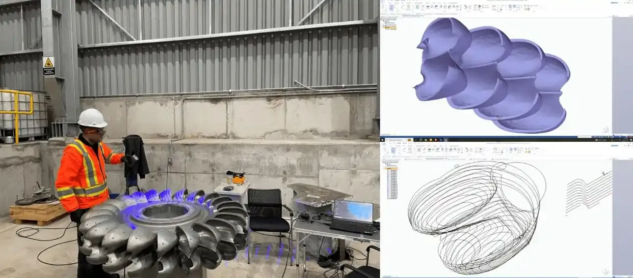
The process starts with sample identification, condition photographs, datum strategy, and a measurement plan. Industrial structured-light or blue-light scanning captures the freeform airfoil and platform as a dense point cloud or mesh. Contact measurement is then used for root serrations, datums, and other critical features that require a controlled probing strategy.
- Scanner capability may be as fine as ±0.02 mm under the stated setup and part conditions; it is not a blanket uncertainty claim for every point on every blade.
- CMM equipment may resolve selected features to ±0.005 mm under a suitable program and environment; the report should state the method and applicable measurement uncertainty.
- Typical outputs include condition photographs, scan data, an aligned mesh, CMM results, and a list of inaccessible or damaged areas.
NIST notes that structured-light scanner results depend on sensor configuration, projected patterns, target geometry, and other setup variables. That is why the measuring method and uncertainty must be matched to each characteristic rather than reduced to one universal accuracy number. See the public NIST overview of structured-light 3D scanner error sources.
2
Separate Wear from Design Intent
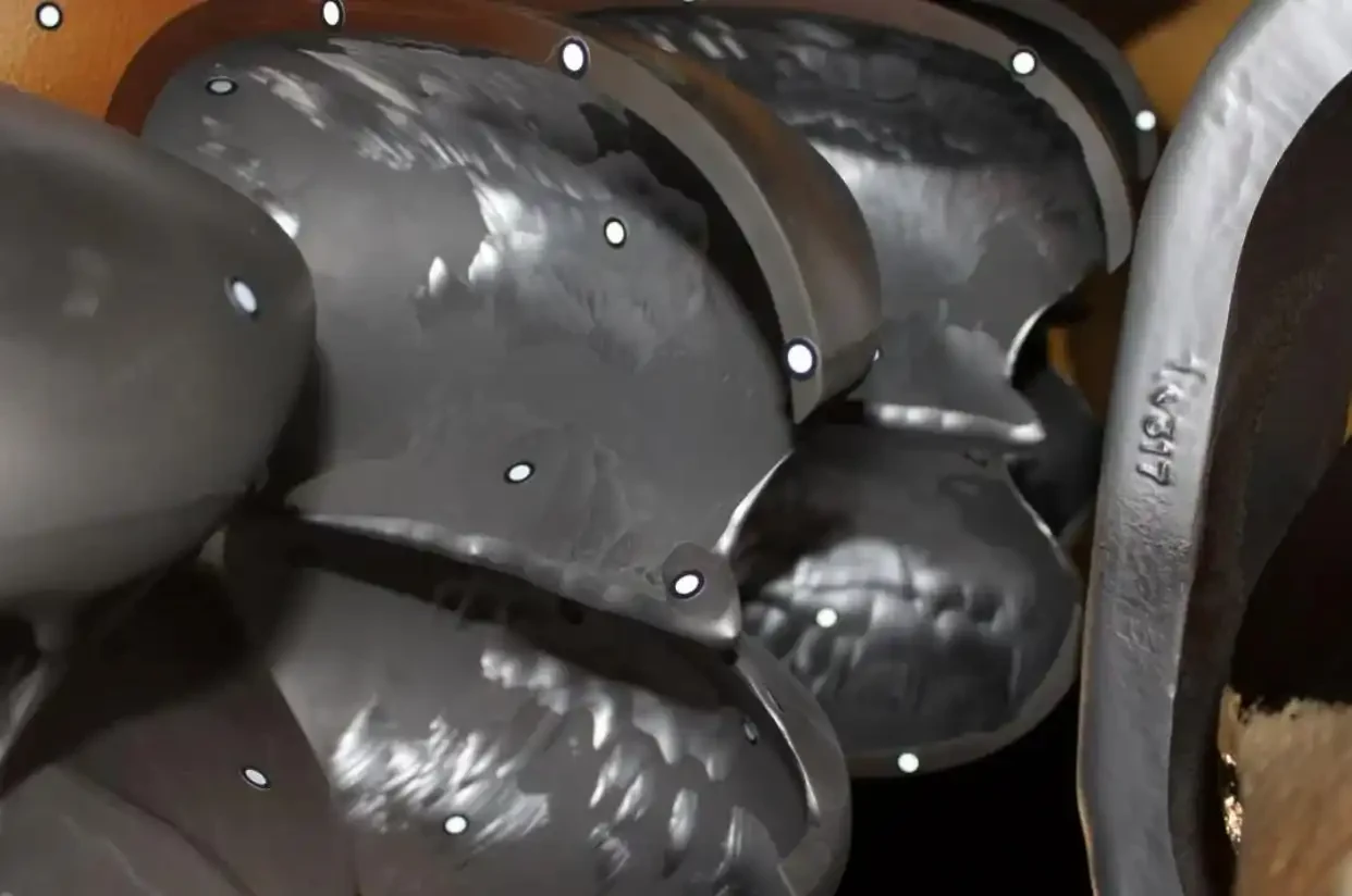
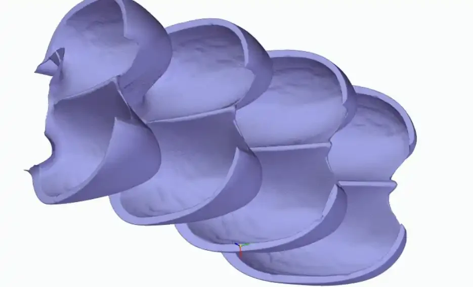
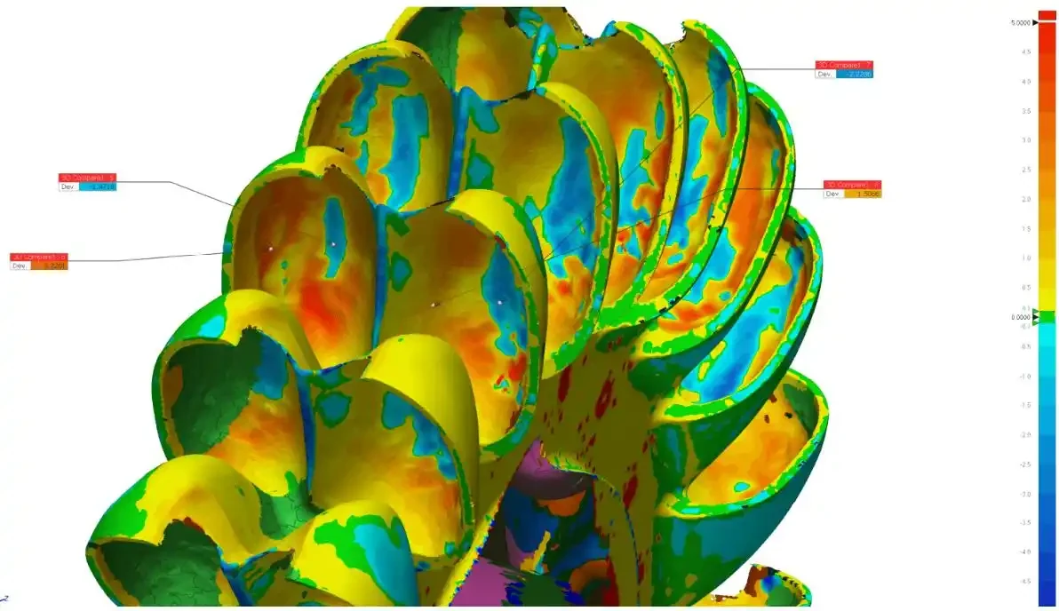
Engineers align the measured datasets to a documented datum system and create deviation maps. Symmetry, repeated sections, neighboring blades, fit relationships, and surviving nominal surfaces help identify which regions are trustworthy. Damaged leading and trailing edges should be reconstructed as controlled assumptions, not silently smoothed until the model looks complete.
Every reconstructed area should be classified as measured, derived, or customer-approved. This decision log is especially important when creep or erosion has changed the airfoil, because dimensional conformity to the worn sample does not prove aerodynamic or fatigue suitability.
3
Build Parametric CAD and an Approval Drawing
The recovered geometry is rebuilt as editable parametric CAD rather than delivered only as an STL mesh. Section curves, airfoil surfaces, root geometry, platform, shroud features, radii, and machining allowances are defined so they can be inspected and revised.
- Neutral deliverables can include STEP, IGES, and Parasolid.
- Native CAD may be supplied when agreed in the project scope.
- A 2D approval drawing identifies datums, critical characteristics, tolerances, surface finish, material, heat treatment, coating, and inspection requirements.
- GD&T should follow the customer-selected drawing standard, such as ASME Y14.5 or ISO GPS conventions. This public GD&T explanation describes how datum-based controls communicate functional design intent.
The owner or designated turbine engineer should approve the model, drawing, and unresolved assumptions before material is released for production.
4
Confirm Material and Special-Process Requirements
Material cannot be selected from appearance or hardness alone. If the original specification is unavailable, identification may require positive material identification, chemical analysis, hardness testing, metallography, or other laboratory work. Candidate alloys such as precipitation-hardening or chromium stainless steels are examples only; they must not be substituted without engineering approval.
After the specification is approved, procurement should preserve heat or lot identity through cutting, heat treatment, machining, and final inspection. A material test report records the supplied heat's reported chemical and mechanical results, but the document does not by itself prove blade fitness for service. The public mill test report overview explains the document's traceability role.
The purchase specification should also identify any required heat treatment, coating, passivation, shot peening, nondestructive examination, or independent laboratory testing. Certificates must reference the same part, heat, and process route shown in the traveler.
5
Machine, Inspect, and Assemble the Verification Dossier
Five-axis CNC machining is commonly used for the airfoil and root because it provides controlled tool orientation across freeform surfaces. In-process probing and dedicated fixtures can maintain the approved datum strategy from roughing through final inspection.
- ±0.05 mm may be a practical machining target for selected features, but it is not a universal acceptance limit for the complete blade.
- ISO 2768 general tolerances apply only to dimensions without individual tolerance indications; critical root, airfoil, shroud, and mating characteristics require explicit customer-approved limits.
- CMM inspection should report the approved critical characteristics and the measurement method used.
- An FAI-style report can provide a ballooned drawing and characteristic-by-characteristic results. AS9102 formatting is used only when contractually required because AS9102 is an aerospace documentation standard, not a general steam-turbine certification.
NIST's public guidance on CMM measurement uncertainty explains why a machine specification alone is not sufficient for a task-specific conformance statement.
What Documentation Should Accompany a Replacement Blade?
A reviewable manufacturing dossier should normally include:
- approved 3D CAD model and controlled 2D drawing;
- measurement plan, scan/CMM records, and reconstruction decision log;
- material specification, purchase record, heat number, and MTR;
- heat-treatment and special-process certificates where applicable;
- manufacturing traveler linking the finished blade to the material heat and process route;
- final dimensional report and ballooned inspection drawing;
- nonconformance and concession records, if any;
- packaging, preservation, and part-identification records.
Additional validation may include NDT, metallurgical testing, modal or frequency checks, mass and moment matching, rotor-fit verification, balancing, overspeed testing, vibration review, or life assessment. The turbine owner and qualified engineering authority must define which of these are required for the specific machine and jurisdiction.
Comparison: Controlled Reverse Engineering vs. Copy Machining
| Feature | Controlled Reverse Engineering | Copy Machining Without an Approved Definition |
|---|---|---|
| Source data | Combines scan, CMM, fit data, records, and engineering review. | Treats one worn sample as nominal. |
| Design intent | Separates measured, derived, and approved geometry. | May reproduce erosion, creep, blending, and damage. |
| Material control | Uses an approved specification with heat/lot traceability. | May rely on an assumed alloy or generic certificate. |
| Inspection | Verifies explicit critical characteristics against an approved drawing. | Checks only convenient dimensions or the copied surface. |
| Deliverables | CAD, drawing, decision log, material records, traveler, and inspection dossier. | Part only, with limited evidence. |
| Lead time | Quoted after sample condition, material, processes, and approval route are known. | Often quoted before technical uncertainty is resolved. |
Procurement Questions to Ask Before Placing an Order
- Which surfaces and features are directly measured, and which are reconstructed assumptions?
- Who approves the recovered airfoil and root geometry?
- How is the material heat number maintained through all subcontracted processes?
- Which characteristics have task-specific measurement uncertainty suitable for their tolerance?
- Which NDT, heat treatment, coating, balancing, or performance-validation steps are required?
- What happens if inspection data conflicts with the approved CAD or drawing?
- Who has final authority to approve installation and return to service?
Clear answers turn reverse engineering from an undocumented copy exercise into a controlled engineering and procurement process.
FAQ
Can a steam turbine blade be manufactured without OEM drawings?
A manufacturing definition can be reconstructed from a physical sample when adequate geometry, fit data, operating requirements, and material information are available. The recovered CAD and assumptions must be reviewed and approved by the turbine owner or qualified engineering authority before production and installation.
Do material certificates prove that a replacement blade is safe to operate?
No. An MTR supports heat-level material traceability and reports specified test results. Fitness for service also depends on the approved alloy and heat treatment, geometry, manufacturing quality, NDT, rotor compatibility, operating conditions, and any validation required by the responsible engineering authority.
How is root fit verified?
Root serrations, datums, contact surfaces, and related rotor-slot requirements are defined on the approval drawing and checked with suitable contact metrology, gauges, or fit verification. The inspection report should identify the measured characteristics, results, and applicable uncertainty.
Is the lead time always 3–5 weeks?
No fixed lead time applies to every turbine blade. A 3–5 week production window may be feasible after sample receipt and drawing approval for some projects, but alloy availability, laboratory analysis, heat treatment, NDT, coating, customer approvals, and validation can extend the schedule. The quoted plan should identify these dependencies.
Does deviation analysis recover the original aerodynamic profile automatically?
No. Deviation maps show differences between aligned datasets; they do not determine the correct nominal profile by themselves. Engineers must combine surviving geometry, repeated sections, companion parts, fit data, historical records, and customer review to justify the recovered design intent.
Regulatory and Engineering Responsibility Notice
Reverse engineering records, material certificates, and dimensional inspection do not constitute turbine performance certification, regulatory approval, or authorization to return a blade to service. Final material selection, stress and life assessment, NDT, rotor compatibility, balancing or overspeed requirements, installation approval, and fitness-for-service decisions remain with the turbine owner, OEM where applicable, and qualified engineering authority. Mechonus manufactures and documents parts to customer-approved requirements.
Conclusion
A replacement steam turbine blade should be sourced as an evidence chain, not as a visual copy. The strongest project connects condition assessment, measurement uncertainty, recovered design intent, approved material and processes, traceable manufacturing records, and final inspection in one controlled dossier.
Mechonus supports the measurement, CAD reconstruction, manufacturing, and inspection portions of that workflow. Review our reverse engineering services and 5-axis CNC machining services to plan the applicable scope.