Core structure
Spiral heating-channel architecture and a high-precision concentric circular layout.

Representative reverse engineering case · semiconductor equipment
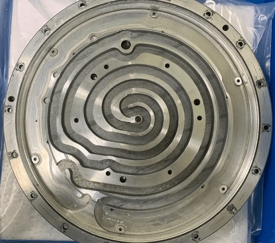
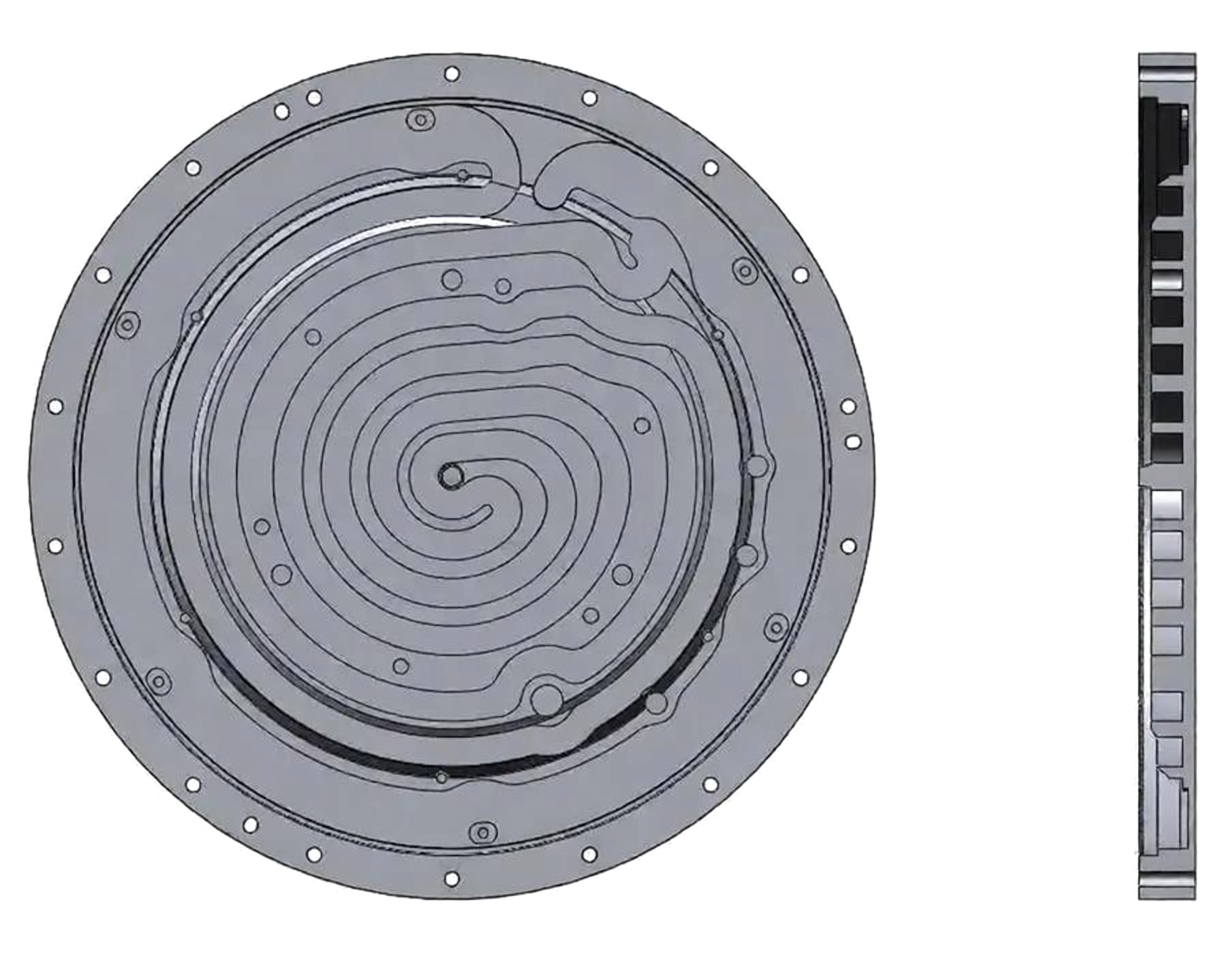
A Ø374 mm semiconductor wafer heater disk with spiral heating channels, concentric geometry and dense sealing-hole features was reconstructed for a European equipment maintenance service provider—turning an unsupported physical part into inspectable, CNC-ready manufacturing data.
The challenge
In semiconductor process equipment, a wafer heater disk is part of the thermal-control system. Its spiral heating channels, concentric layout and sealing interfaces must work as one controlled geometry. When the OEM drawing was lost, an imported spare brought both an extended supply route and a high cost the customer could not accept.
The Ø374 mm sample presented three linked risks: small concentricity errors can disturb the thermal field; dense screw-hole position controls affect sealing and long-term stability; and a simple scan-to-surface copy would not create the no-draft, machining-aware model required for direct CNC programming. Individual calliper or point-by-point CMM measurements could not reliably describe this full spatial relationship.
Specification
The project concentrated on spiral channels, a high-precision concentric layout and critical sealing-hole geometry. The engineering goal was to preserve these functional relationships in a definition that can be inspected, programmed and machined—not just displayed as a 3D scan.
Spiral heating-channel architecture and a high-precision concentric circular layout.
Coaxiality and fastener-hole positional accuracy directly affect sealing and long-term process stability.
ZEISS GOM Scan 1 structured-blue-light acquisition, with 0.01 mm-class measurement capability and up to 6 million points per frame.
No-draft parametric CAD, controlled 2D drawing, STP/IGS data and direct CNC/CAM-ready output.
The approach
The deliverable is not an isolated STL file. It is an editable, inspectable definition that locks the common axis, retains the relationships among channels, holes and seating faces, and gives CNC/CAM and inspection teams an unambiguous manufacturing reference.
The returned disk was registered with its orientation, seating faces, bores, ports and dense fastener pattern. The spiral heater-channel layout and concentric relationships were recorded before cleaning or scanning changed the available evidence. A primary mounting plane and rotational axis were then established as the datum hierarchy for all later work.
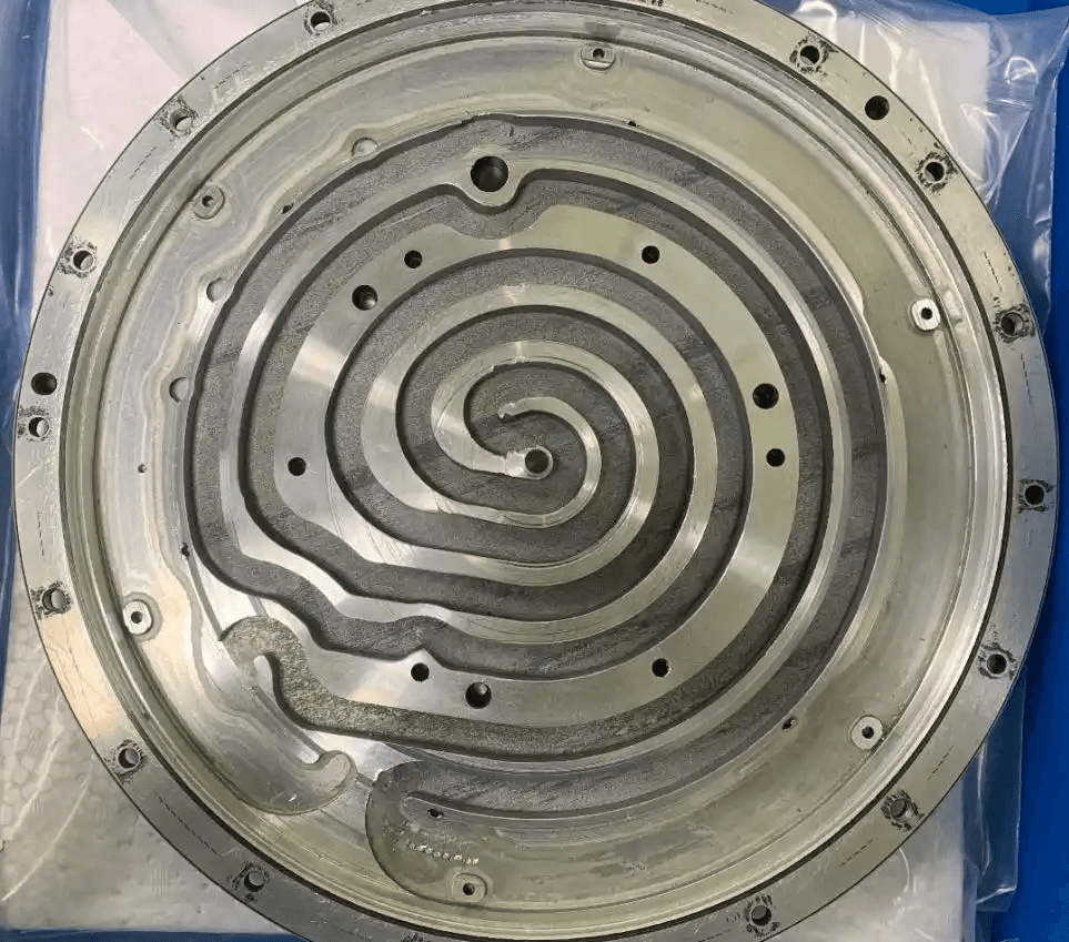
A ZEISS GOM Scan 1 blue-light system captured the external form, circular features, spiral channels and dense hole positions. With 0.01 mm-class measurement capability and up to six million points per frame, the acquisition plan used overlapping views, targets and controlled surface preparation to retain detail on the large, reflective machined disk.
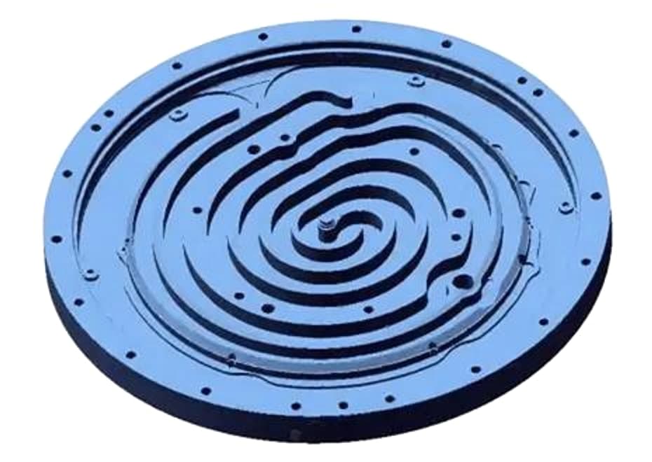
Automated mesh conditioning reduced noise while preserving machined edges, channel boundaries and small holes. The mesh was sectioned around the established centreline; channel paths, concentric rings, counterbores, locating features and mounting-hole centres were extracted before any parametric feature was created.
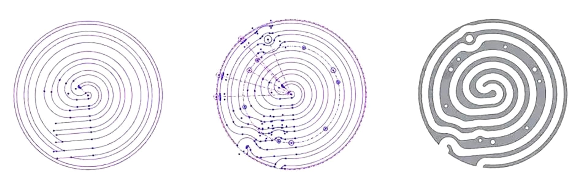
The team did not simply fit free-form surfaces to the point cloud. Standard concentric sketches were derived from section analysis, the base plate was rebuilt 1:1 as native solid geometry, and the channel, locating-hole and screw-hole relationships were recreated around measured centre distances. The resulting no-draft parametric model is structured for direct CNC programming.
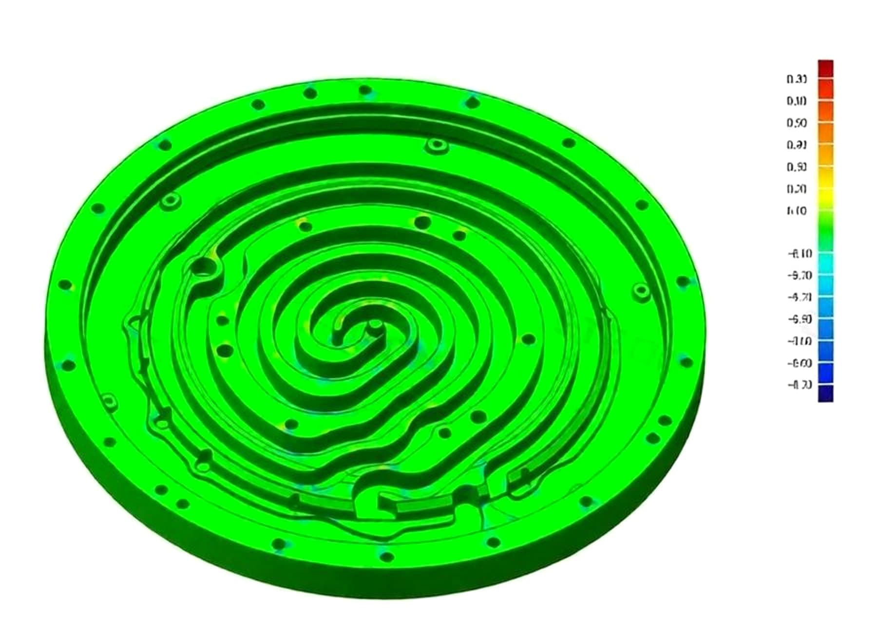
The reconstructed CAD was compared with the original scan using full-surface colour mapping, supplemented by targeted dimensional checks at sealing faces and hole locations. Overall form, concentricity and critical hole locations were evaluated in a controlled ≤ 0.01–0.10 mm band according to feature access and the agreed inspection method before CAD and drawing release.
Detailed engineering process
Each gate reduces a distinct source of uncertainty: alignment, reflective-surface acquisition, feature identification, parametric intent, acceptance criteria and manufacturing readiness. The evidence remains linked to the released revision.
Document equipment function, operating temperatures, interfaces, sample condition, available service history and the customer’s intended acceptance criteria. Identify what must be recovered and what requires further confirmation.
OutputApplication brief + sample registerSelect the primary mounting plane, rotational axis and locating features. Define scan orientations, targets, anti-glare preparation and independent checks for holes, ports and concealed areas.
OutputDatum strategy + acquisition planCollect overlapping structured-light views, validate alignment quality and retain raw point-cloud / mesh evidence. Use additional feature measurements where a scan cannot establish a critical datum or internal condition with confidence.
OutputAligned scan dataset + measurement recordRemove noise while preserving machined boundaries; isolate circular features, plane relationships, counterbores and hole centres. Compare repeated patterns and section data before any CAD assumption is made.
OutputProcessed mesh + feature mapRebuild the disk through controlled sketches, planes, axes and native solid features. Concentric relationships, dense fastener locations and machining-facing geometry remain editable for later service, revision or production use.
OutputEditable parametric CAD modelTranslate the approved model into a 2D manufacturing drawing with datums, critical dimensions, positional tolerances and inspection references. Define the evidence required for the first article and any future repeat order.
Output2D drawing + inspection planReview the CAD, drawing, outstanding assumptions and dimensional comparison with the customer before manufacturing release. Approved revisions become the sole source for CAM and inspection programming.
OutputCustomer-approved release packageIssue the native / neutral model and manufacturing package in formats compatible with the customer’s chosen workflow. The data supports direct CNC/CAM programming rather than a second round of reverse engineering at the machine shop.
OutputSTP/IGS + drawing + CNC/CAM dataDeliverables
Reverse engineering ends on the shop floor, not in a viewer. The released package gives the production and quality teams an inspectable source of truth, without a second supplier needing to redraw or reinterpret a raw mesh.
“The missing drawing had become the bottleneck. The recovered model gave our production partner a usable definition and gave us an inspection baseline for future service work.”Technical Manager, Semiconductor Equipment Maintenance Provider
This case is based on an actual delivered project. Customer information and selected technical parameters have been anonymized. To discuss a similar reverse engineering project, submit your part information through our website and our engineering team will provide an initial assessment.
Missing drawings do not end the engineering path
Share photos, dimensions, machine context, operating conditions and any available inspection or service records. We will define the evidence needed for a controlled replacement program.